
This began as a routine asset discovery scan on an OT network—no exploits, no malicious intent. Within 30 seconds, the HMI went red and the PLC stopped responding. No system was compromised. The scan itself caused the incident.
At first glance, the scan looked harmless. But it exposed a critical gap between IT security tools and OT environments—where protocol assumptions don’t translate cleanly. Tools like Nmap are designed to probe flexible, fault-tolerant IT systems. Industrial control systems are not.
What followed wasn’t a breach, but a breakdown in communication at the protocol level—one that briefly disrupted operations. Understanding why this happens is key to securing modern OT environments.
Here’s exactly what happened at the packet level and why it matters.
How Modbus/TCP normally works in ICS environments
Let’s start with a normal Modbus Read Holding Registers request from a Master to a Slave PLC. This is what your PLC expects to see (Packet structure) on port 502.
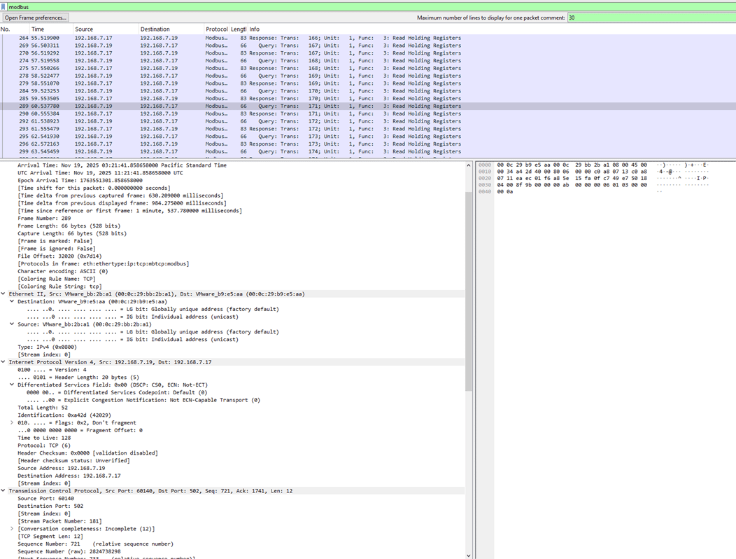
Figure 1: A Packet capture between Modbus master and slave for read holding registers
Hex dump (simplified):
0000 00 0c 29 b9 e5 aa 00 0c 29 bb 2b a1 08 00 45 00
0010 00 34 a4 2d 40 00 80 06 00 00 c0 a8 07 13 c0 a8
0020 07 11 ea ec 01 f6 a8 5e 15 fa 0f c7 49 e7 50 18
0030 04 00 8f 9b 00 00 00 ab 00 00 00 06 01 03 00 00
0040 00 0a
Ethernet header
00 0c 29 b9 e5 aa = Destination MAC (PLC’s MAC address)
00 0c 29 bb 2b a1 = Source MAC (master/HMI)
08 00 = Ethernet Type IPv4
IPv4 header
45 = Version 4, header length 20 bytes
00 = Differentiated Services field
00 34 = Total length (52 bytes)
a4 2d = Identification (42029), used for fragment reassembly (this packet isn’t fragmented)
40 00 = Flags and Fragment Offset: “Don’t fragment”, offset 0
80 = Time to live (128)
06 = Protocol TCP
00 00 = Header checksum (disabled in this capture)
c0 a8 07 13 = Source IP address (192.168.7.19) c0 a8 07 11 = Destination IP address (192.168.7.17)
TCP header
ea ec = Source port (60140)
01 f6 = Destination port (502 – Modbus/TCP)
a8 5e 15 fa = Sequence number (raw 2824738298) – byte offset in the TCP stream where this packet’s data begins
0f c7 49 e7 = Acknowledgment number (raw 264718823) – next byte expected from the peer
50 = TCP header length (20 bytes)
18 = Flags (PSH, ACK)
04 00 = Window size (1024)
8f 9b = TCP checksum
00 00 = Urgent pointer (0, no urgent data)
Modbus Application Data Unit (ADU)
00 ab = Modbus Transaction Identifier (171)
00 00 = Modbus Protocol Identifier (always 0 for Modbus/TCP)
00 06 = Modbus Length (6 bytes of data follow: Unit ID + PDU)
01 = Unit Identifier (slave address 1)
03 = Function code (Read Holding Registers)
00 00 = Reference number (starting register address 0)
00 0a = Word count (10) – number of 16-bit registers to read
Everything is consistent: correct protocol ID, a small and realistic length, a valid Unit ID, and a standard function code. The PLC happily processes this and returns the requested register values.
Figure 2: Modbus Packet Deconstruction
What happens when Nmap scans a Modbus Port (Port 502)
Now, let’s look at what happens when you run:
sudo nmap -p 502 192.168.7.17 -sC -sV
Nmap opens a TCP connection to port 502 and sends a generic HTTP OPTIONS request to fingerprint the service. That’s fine for a web server, but this target is a PLC waiting for Modbus.
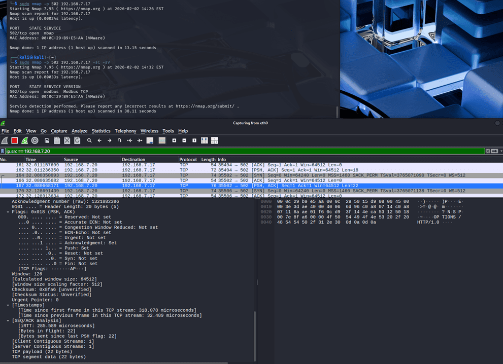
Figure 3: Nmap scan on Modbus slave
Hex dump (simplified):
0000 00 0c 29 b9 e5 aa 00 0c 29 50 15 d9 08 00 45 00
0010 00 3e 3d ae 40 00 40 06 6d 96 c0 a8 07 14 c0 a8
0020 07 11 8a ae 01 f6 0c d9 3f 14 4e ca 53 12 50 18
0030 00 7e 8f a6 00 00 4f 50 54 49 4f 4e 53 20 2f 20
0040 48 54 54 50 2f 31 30 0d 0a 0d 0a
Ethernet header
00 0c 29 b9 e5 aa = Destination MAC (PLC)
00 0c 29 50 15 d9 = Source MAC (scanner)
08 00 = IPv4
IPv4 header
45 = Version 4, header length 20 bytes
00 = Differentiated Services field
00 3e = Total length (62 bytes)
3d ae = Identification (15790)
40 00 = Flags: “Don’t fragment”, Fragment offset 0
40 = Time to live (64)
06 = Protocol TCP
6d 96 = Header checksum (validation disabled here)
c0 a8 07 14 = Source IP address (192.168.7.20)
c0 a8 07 11 = Destination IP address (192.168.7.17)
TCP header
8a ae = Source port (35502)
01 f6 = Destination port (502)
0c d9 3f 14 = Sequence number (raw 215564052)
4e ca 53 12 = Acknowledgment number (raw 1321882386)
50 = TCP header length (20 bytes)
18 = Flags (PSH, ACK)
00 7e = Window size (126)
8f a6 = TCP checksum (unverified)
00 00 = Urgent pointer
Payload: HTTP, Not Modbus
Payload bytes
• 4f = O • 50 = P • 54 = T • 49 = I
• 4f = O • 4e = N • 53 = S • 20 = space
• 2f = / • 20 = space • 48 = H • 54 = T
• 54 = T • 50 = P • 2f = / • 31 = 1
• 30 = 0 • 0d = CR • 0a = LF • 0d = CR
• 0a = LF
In ASCII, that’s:
OPTIONS / HTTP/1.0\r\n\r\n
From an IT perspective, this is a harmless banner‑grab. From the PLC’s point of view, it’s nonsense hitting a critical port.
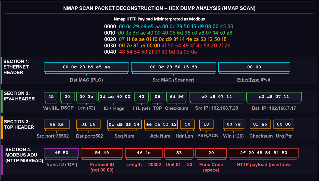
Figure 4: NMAP Scan Packet Deconstruction
| Field | Expected | Received | Result |
| Protocol ID | 00 00 | 54 49 | Rejected |
| Length | ≤ 256 | 20302 | Socket hangs |
| Unit ID | 01–247 | 83 | Not addressed |
| Function Code | 01–127 | 20 (space) | Invalid |
| Fields after Function code | None | 2f 20 48 54 54 50 | Overflow |
Table 1: Summary of difference
Why PLCs misinterpret non-Modbus traffic (Packet breakdown)
A Modbus/TCP server expects the first bytes of payload to form the Modbus Application Data Unit header:
Bytes 0–1: Transaction Identifier
Bytes 2–3: Protocol Identifier (must be 0x0000 for Modbus/TCP)
Bytes 4–5: Length (Unit ID + PDU bytes)
Byte 6: Unit Identifier
Byte 7+: Modbus PDU (Function code and data)
Let’s map the HTTP payload on to those positions and see what goes wrong, byte by byte.
Supposed “Modbus” bytes (actually HTTP):
4f 50 54 49 4f 4e 53 20 2f 20 48 54 54 50 2f 31 30 0d 0a 0d 0a
Transaction ID
Expected: Any 2‑byte number that the client will use to match the reply.
Seen in packet:
Bytes 0–1: 4f 50 → ASCII “OP” (start of OPTIONS).
This is weird but technically still a valid “transaction id” if the device doesn’t sanity‑check it. On its own, it doesn’t break the packet.
Protocol Identifier
Expected: 00 00 for Modbus/TCP. Any other value means “not Modbus.”
Seen in packet:
Bytes 2–3: 54 49 → ASCII “TI”.
This is the first real show‑stopper: a proper implementation should immediately reject the request because the Protocol ID does not equal 0x0000. The PLC effectively thinks: “This is not Modbus; I should ignore or reset this connection.”
Length Field
If, however, the firmware is sloppy and continues parsing:
Expected: A small value, representing the number of bytes following (Unit ID + PDU). Typical values are under 256.
Seen in packet:
Bytes 4–5: 4f 4e.
Interpreted as a big‑endian integer, 0x4f4e = 20,302. That means:
- The PLC believes it must receive 20,302 additional bytes to complete this “Modbus” frame.
- The HTTP request is only a few dozen bytes long, so the rest of the data never arrives.
- The PLC may keep the socket open, waiting for data that will never come, until a timeout cleans it up.
This single bogus length field is enough to consume connection slots on the PLC while it waits.
Unit Identifier
Expected: A valid Unit ID like 01, 02, 03, or sometimes 00/FF for broadcast.
Seen in packet:
Byte 6: 53 → ASCII “S”.
Now the PLC sees a unit address of 83 decimal. That’s unlikely to exist in a small lab setup and may not map to any configured slave. The device may decide this is “not addressed to me” and drop it.
Function Code
Expected: Known Modbus function codes – 01 (Read Coils), 02 (Read Discrete Inputs), 03 (Read Holding Registers), 04 (Read Input Registers), 05, 06, 0F, 10, etc.
Seen in packet:
Byte 7: 20 → ASCII space (decimal 32).
This is not a valid standard Modbus function code. If parsing continues this far, the PLC cannot map 0x20 to any operation and should reject the PDU as malformed.
“Data” Overflow
The remaining bytes (2f 20 48 54 54 50 2f 31 30 0d 0a 0d 0a) are just the rest of the HTTP request, but if the PLC still believes the length is 20,302, it treats these as the very beginning of a huge payload that never finishes.
From the PLC’s perspective:
- Transaction ID: random ASCII instead of a clean client‑chosen value.
- Protocol ID: wrong (54 49 instead of 00 00).
- Length: absurd (20 KB instead of a small PDU).
- Unit ID: unlikely and not configured.
- Function code: invalid.
No part of this payload matches what a Modbus/TCP server is supposed to see.
Summary: What each byte field means for the PLC
| Field | Expected | Received | PLC Result |
| Protocol ID | 00 00 | 54 49 | Immediately rejected |
| Length | ≤ 256 | 20,302 | Socket hangs waiting for data |
| Unit ID | 01–247 | 83 | Not addressed to any slave |
| Function Code | 01–127 | 0x20 (space) | Invalid — PDU rejected |
Table 2: Modbus Header Fields: Expected vs. Received
How a simple scan turns into an OT Denial-of-Service event
So far, this is “just a bad frame.” The real problem starts when you realize how many such frames a typical nmap scan can generate.
A plausible sequence in a real environment looks like this:
- Nmap launches many parallel connections
- With default or aggressive timing, nmap sends dozens or hundreds of SYNs to port 502.
- PLC accepts connections, table fills
- Each new TCP session consumes a connection slot; many PLCs only support a small number (e.g., 16–64).
- Nmap sends OPTIONS / HTTP/1.0 over each session
- Every connection carries the malformed “Modbus” payload we analysed above.
- PLC detects mismatches
- The Protocol ID, length, Unit ID, and function code all fail validation; the device may respond with TCP RSTs or just silently drop.
- Sockets hang around
- Because of the bogus length and waiting for more data, or simply due to slow cleanup, these connections can remain in various states for several seconds.
- Legitimate HMI is temporarily blocked
- When an HMI or SCADA server tries to open or maintain its own Modbus session during this window, it sees “Connection refused” or timeouts because the PLC’s connection table is busy with scan traffic.
- After a short delay, things recover
- Once old sockets time out or are reset, the table frees up; HMI retries and connects successfully, usually within 5–10 seconds.
- Operations continue, but with a visible glitch
- Operators may see red indicators, stale values, or “lost communication” alarms during the brief interruption.
No exploit was used. The PLC wasn’t compromised. The attack is purely about availability: a poorly tuned, protocol‑agnostic scan created a small denial of service on a critical control protocol.
A timeline of the incident (approximate)
- T+0s — Nmap begins SYN sweep to port 502
- T+2s — PLC connection table saturates (16/16 slots occupied)
- T+3s — HMI Modbus poll times out; process tags go stale
- T+5s — Operator sees “Communication Lost” alarm on HMI
- T+12s — Nmap finishes; sockets begin timing out
- T+18s — PLC recovers; HMI reconnects and tags refresh
Figure 5: Malformed Modbus packet reported by Wireshark Modbus dissector
Figure 6: PLC sending a Reset communication request
Key lessons for securing ICS and OT networks
This case study highlights why ICS and OT networks must be treated differently from IT when it comes to scanning and enumeration.
- Generic scans don’t understand industrial protocols: Tools like nmap are built around assumptions that work fine for HTTP, SSH, SMTP, and similar IT protocols. For Modbus/TCP, the “banner” is the protocol behavior itself. A PLC expects a strict binary structure, not ASCII verbs.
- PLCs are resource‑constrained and fragile: Many PLCs have:
- Small connection tables.
- Long TCP and application timeouts.
- Minimal input validation, especially on older firmware.
This makes them easy to overwhelm with what would be harmless traffic elsewhere.
- Use protocol‑aware tools and scripts: If you really need to discover or enumerate Modbus devices safely using open-source tools:
- Use Modbus‑aware scanners or nmap scripts that emit valid Modbus headers (With right Protocol ID, right Unit Id and right function codes) such as –script modbus-discover instead of generic scan for port 502.
- Network-level protections: Generic port ACLs are not enough. Apply these controls at the network layer:
- Place PLCs behind a firewall or deep-packet-inspection appliance that enforces Modbus protocol structure — not just TCP port 502 access.
- Rate-limit new TCP connections to port 502 at the switch level (e.g., max 3 new sessions per second per source IP).
- Use VLANs and network segmentation to isolate OT devices from any subnet that IT tools can reach without explicit authorization.
- Disable or restrict ICMP and TCP SYN responses from PLCs to untrusted subnets so they are not discoverable via generic scanners.
Conclusion
The core lesson here isn’t that nmap is dangerous — it’s that IT tools carry IT assumptions into an environment built on completely different ones. A PLC doesn’t have an antivirus, a watchdog thread, or a graceful error handler waiting to catch malformed input. It has a ladder logic program that expects exactly what the protocol specification says, and nothing else.
Before you scan an OT network, ask yourself: does this tool know what Modbus is? If the answer is no, your “safe” scan might be someone else’s incident.